The Planar Array Tool allows user to create multiple copies of an entity along two direction.
From the Toolbar: Find the Linear Tool icon  on the Modify Toolbar (color coded green) and Click on the tool. The tool is now active and ready for use. on the Modify Toolbar (color coded green) and Click on the tool. The tool is now active and ready for use.
From the Shortcut Key: The default shortcut key for the point tool is the letter "Alt + R, 3". Simply press the key and the tool will be activated.
From the Command Line: Type "array_planer" into the Command Line, at the top of the notification window, and press the Enter/Return key.
|
This tool is a Stacked Tool; if there is no selection prior to the activation of this tool the Selection Tool will become active. If entities were already selected when the tool was activated then this step will be skipped.
1. Select entities to create array.
2. Press Enter to finish the selection process.
|
1. Set Array Tool Settings:
| • | "Array Mode" needs to be set to "Planar Array (2D)" to create planar array. |
| • | "Axis Selection" can be set to "WCS Axis" (WCS x-axis is column offset direction and y-axis is row offset direction), or "UCS Axis" (UCS x-axis is column offset direction and y-axis is row offset direction), or "Arbitrary Axis" (Define your own column and row offset directions). |
| • | If "Delete Entity" is checked, the original entity from which the array is created gets deleted after inserting array. |
| • | "Row Offset" specifies the unit offset distance between rows. |
| • | "Column Offset" specifies the unit offset distance between columns. |
| • | "Number of Columns" specifies the number of columns. |
| • | "Number of Rows" specifies the number of rows. |
2. If "Arbitrary Axis is not selected as "Axis Selection" this step is skipped. Move the mouse and Click on the drawing. This will be the start point of column offset direction. Move the mouse and click on the drawing again. This will be the end point of column offset direction.
3. If "Arbitrary Axis" is not selected as "Axis Selection" this step is skipped. Move the mouse and click on the drawing. This will be the start point of row offset direction. Move the mouse and click on the drawing again. This will be the end point of row offset direction.
4. Move the mouse and click on the drawing. This will be the base point of the Planar array.
5. Move the mouse and click on the drawing. The planar array will be inserted at this insertion point.
Reset:
After cloning entities the tool will automatically reset. You can either continue with other tools or array more entities.
|
To create Planar Array from the selected entity(ies) in a more precise manner go to the Tool Property Tree.
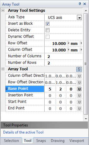
1. Set array tool settings:
| • | "Array Mode" needs to be set to "Planar Array (2D)" to create planar array. |
| • | "Axis Selection" can be set to "WCS Axis" (WCS x-axis is column offset direction and y-axis is row offset direction), or "UCS Axis" (UCS x-axis is column offset direction and y-axis is row offset direction), or "Arbitrary Axis" (Define your own column and row offset directions). |
| • | If "Delete Entity" is checked, the original entity from which the array is created gets deleted after inserting array. |
| • | "Row Offset" specifies the unit offset distance between rows. |
| • | "Column Offset" specifies the unit offset distance between columns. |
| • | "Number of Columns" specifies the number of columns. |
| • | "Number of Rows" specifies the number of rows. |
2. If "Arbitrary Axis" is not selected as "Axis Selection" this step is skipped. Type in column offset direction data into the "Column Offset Direction" 3D Vector found on the Tool Property Tree and press Enter to accept.
3. If "Arbitrary Axis" is not selected as "Axis Selection" this step is skipped. Type in row offset direction data into the "Row Offset Direction" field and press Enter to accept.
4. Type the base point coordinates into the "Base Point" 3D Point Property Field and press Enter to accept.
5. Type the insertion point coordinates into the "Insertion Point" field and press Enter to accept.
Reset:
After cloning entities the tool will automatically Reset. You can either continue with other tools or array more entities.
|
 Right Click: Brings up a Context Menu containing options for this tool. Right Click: Brings up a Context Menu containing options for this tool.
 Escape (Esc): Cancels current tool and activates the default tool (Selection Tool). Escape (Esc): Cancels current tool and activates the default tool (Selection Tool).
Space: Resets this tool.
|
Also See:
Selection Tool
Grid
Grid Snaps
Entity Snaps
Notification Bar


|


