Planar Polyline Tool

Getting Started  Previous  Next

The planar polyline tool is responsible for creating (2d) Planar Polyline Entities.


Creating a Planar Polyline:

From the Toolbar: Find the planer polyline tool icon ssEntity2DPolylinel on the Entity Toolbar (color coded blue) and Click on the tool. The tool is now active and ready for use.

 
From the Shortcut Key: The default shortcut key for the point tool is the letter "P". Simply press the key and the tool will be activated.

 
From the Command Line: Type "planer_polyline" into the command line, at the top of the Notification Window, and press the Enter/Return key.


1. Click on the drawing to specify the first point. This will add a polyline vertex and set the previous point field to this value.

2.  If you have only placed one one vertex, then you must place another in the same manner (or via the property tree or consol) to successfully create a polyline.

3.  If in specify length mode move the mouse and click when the line is at the desired length.

4.  Repeat Step 1, 2 ,and 3 until all desired vertices have been added.

5.  Press keyboard_20 Shift+Enter to finish the polyline and and add it to the drawing.


Reset:

After working through the necessary steps, the polyline is added to the drawing. The tool automatically resets and you can either move on to other tools or add in another polyline. Using reset (Space Bar) at any time while using this tool cancels all previous steps and restarts the tool.


To add a planar polyline using typed data open the Tool Tab in the property tree.

ssPolylineToolProperties


1.  Type the current point coordinates into the "Current Point" 3D Point Property Field and press Enter to accept. This will add a polyline vertex at this location and set the previous point to this value.

2.  If only one vertex has been added, then you must place another in the same manner (or using the mouse or console) to successfully create a polyline.

3.  If specify length mode is enabled, type in the length data into the "Length" Scientific Data Field found and press Enter to accept.

4.  Repeat Step 1, 2 ,and 3 until all desired vertices have been added.

5.  Press keyboard_20 Shift+Enter to finish and add the polyline to the drawing.


Reset:

You have just added a planar polyline to the drawing with vertices at the designated locations. The tool automatically resets and you can either move on to another tool or add another planar polyline. Using reset (Space) at any time while using this tool cancels all previous steps and restarts the tool.


mouse_20 Right Click: Brings up a Context Menu containing options for this tool.

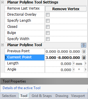
Remove Last Vertex: Removes the last placed vertex, so that the user can place it where at an adjusted location. Can continue to remove vertices until there is one left. Then the user must reset the tool if s/he doesn't want to retain the remaining vertex.

Directional Overlay: Displays an overlay of an arc and a text displaying the angle of the line direction from the x-axis. When this option is enabled the user also gets the option to choose the direction of the overlay measure in the Counter Clockwise field.

Specify Length Mode: Allows the user to specify the length of a particular polyline segment as part of the planar polyline creation process.

Draw Closed Mode: Adds a final closing polyline segment from the last point in the polyline back to the first point in the polyline.

Draw Bulge Mode: Allows the user to draw polyline segments as arcs.

Specify Width:  Brings out two fields that ask for the start and end width to use when drawing segments.


keyboard_20 Shift+Enter: This keystroke will finish and add the polyline to the drawing.

keyboard_20 Escape (Esc): Cancels current tool and activates the default tool (Selection Tool).

keyboard_20 Space: Resets this tool.


Also See:

Planar Polyline

Grid

Grid Snaps

Entity Snaps

Notification Bar